The “Smart Garage” is an IoT garage door interface that allows its user to interact with their garage door securely from anywhere in the world. It features an ESP8266 which talks to a Raspberry PI over an authenticated MQTT protocol. The Raspberry PI then mediates communication with the AWS IoT cloud over an encrypted connection. The system was implemented with scalability in mind and could be expanded to include many more “home IoT devices”.
Skip to the very bottom for a full operational video of the device and github links.
Introduction
The idea for automating my garage door came out of one-too-many return trips back home from my way to the office after being unable to convince myself I had closed the garage (operating on morning autopilot). I decided that this was a good opportunity to dive into Internet of Things (IoT) development and build a computer to control and monitor the garage door.
Initial System Design Plan
I didn’t know much about IoT starting out and decided to use a Rasperry PI to monitor an electrical contact in the garage and send me status over the internet. I chose the Raspberry PI because it could be a web server, had wireless connectivity and GPIO ports. Plus, I was already familiar with it from my Mirror Project.
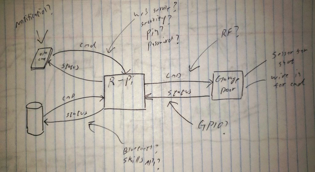
The idea was hazy at first and I quickly realized a few issues with it:
- This was not a scalable solution. The raspberry PI was relatively expensive and adding more IoT devices would quickly add up. Plus, there was no central framework in place that would offer good system reuse.
- The Raspberry PI was complete overkill for this application because the task of interacting with the garage did not require significant processing.
- Hard-wiring some sort of electrical detection would be ugly and difficult to maintain.
Revised System Design Plan
I spent some time researching and realized that having a central computer, such as the Raspberry PI, talking to a much simpler and cheaper microcontroller in the garage would be a better architecture. This way, I could create more of these IoT devices for the house and the interface to the outside world (and system brains) would remain the same.
I researched internal communication protocols and discovered MQTT which seemed perfect for this kind of system due to its simplicity, robust decoupled nature and available documentation. For the garage microcontroller, I settled on the ESP8266. Its 80Mhz CPU, built-in WIFI, 16 GPIOs was more than I needed for a simple garage controller and its $8.00 price tag was the cherry on top. Plus, tons of libraries and community support would speed up development time.
I also devised a contact-less interface to monitor the garage door: by aiming a cheap little acoustic sensor at the ceiling I could detect when the garage door rolled up between the sensor and the ceiling. This would allow for greater flexibility in module placement and avoid hard-wiring.
Prototyping and Implementation
While I didn’t know how the whole system was going to work yet, I had enough to start prototyping.

Initialization State Machine
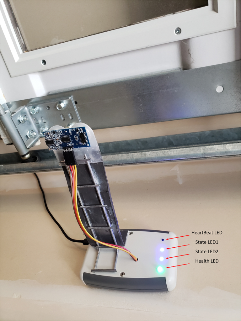
To determine open/closed door, I set up an initialization state machine. This approach allowed me to avoid hard-coding distances in order to tell if the garage door was open or closed. Instead, the device could be arbitrarily mounted and “figure out” its environment on its own. I used some spare LEDs to get visibility into system state.

Actuation of the Garage Door
Once detection was working, it was time to start considering door actuation. In lieu of time, I decided to not reinvent the wheel and used a spare garage remote that I had laying around.
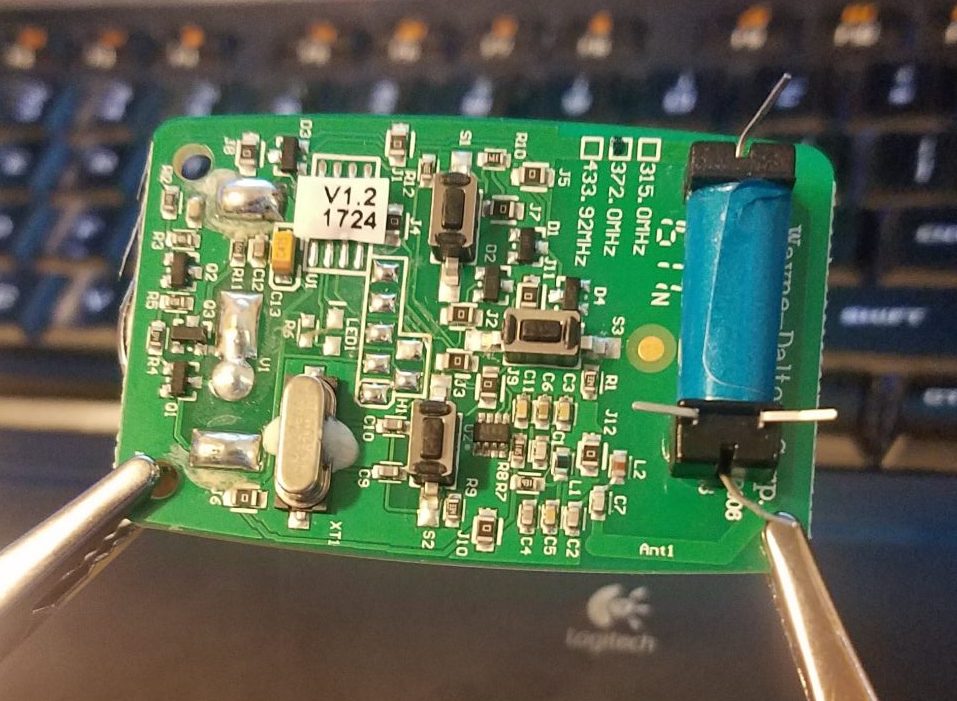
I took apart the remote…

..removed the PCB, and glued a spare relay I had lying around on top.
Then, I soldered it to the main button, so that I could bypass it with a simple +5V from a GPIO pin (500ms of logic-high seemed appropriate).
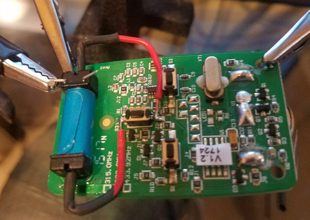
While at it, I stripped out the 3.3V battery and wired it directly to the 3.3V supply on the ESP8266 (the current draw was tiny on the remote and the ESP8266 handled it quite well).

Internal System Communication
It was now time to work on the communication between the ESP8266 and the Raspberry PI. For this, I chose to use Mosquitto – a lightweight open source message broker that implements MQTT. Installing it on the Raspberry PI and setting up a basic user name and password for q&d authentication was very simple. Thanks to great libraries, setting up the ESP8266 to talk to the Raspberry PI was simple as well.

Voila! I now had a fully independent system running on the ESP8266 detecting and reporting two different door states, opening and closing the garage door, and talking to the Raspberry PI via MQTT. Cool!
Next it was time to talk to the Raspberry PI from the outside world.
External System Communication
Because the system controlled an entrance to my home, I needed to connect to it in a secure way. I also wanted to integrate Amazon Alexa so that I could control it from around the house as well as the mobile Alexa app.
Initial Approach to External Communication: Spoofing a Wemo Switch
The first approach I implemented involved spoofing a wemo switch. Someone had already done the work of reverse-engineering a wemo – alexa handshake using wireshark (pic from hackaday below).
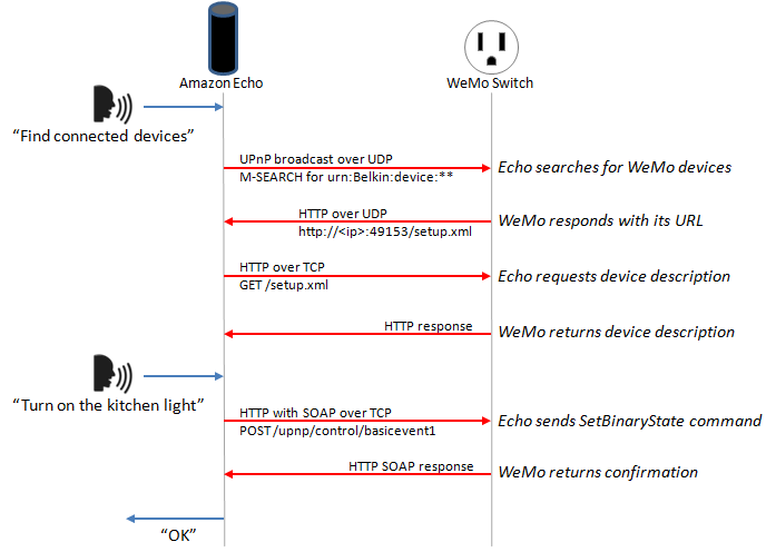
By using this code I was able to set up my Raspberry PI as a Wemo device very quickly. Alexa could then discover “garage” (my Raspbery PI) and I could issue commands such as “turn garage on/off” from my Alexa as well as the mobile app. I edited the code to have the Raspberry PI send an “open” or “close” command down to the ESP8266 over MQTT in response. While this solution worked, it was not what I needed for two major reasons:
- Saying “turn on the garage” was ugly and I couldn’t figure out a way to change it to “open” in a reasonable amount of time.
- Most importantly, this way did not support a query to the garage module so that I could find out its status. This was a major road block because I would never know if the garage was open or closed.
I realized that I would need to write my own Alexa Skill. It looked like the skill would have to connect to an end point, and so I started looking into implementing secure websockets when I stumbled across one of Amazon’s latest and greatest new things allowing me to kill two birds with one stone: the very cool AWS IoT.
Solution to External Communication: Using AWS IoT
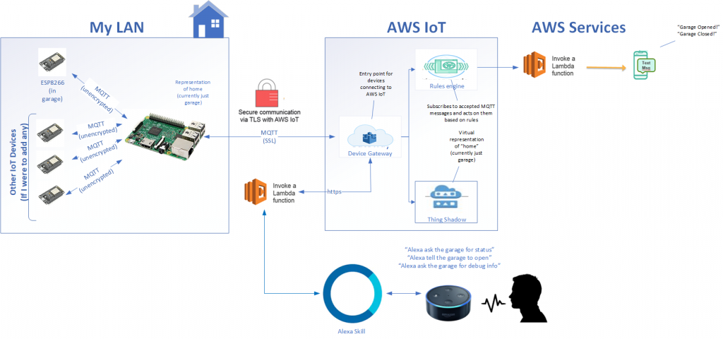
AWS IoT is a cloud service geared towards internet of things devices. Each such device can write status to the cloud and subscribe to events from the cloud securely. In fact, all communication to and from AWS IoT is encrypted with TLS version 1.2 and so this link worked for me. Once in the cloud, I could do a lot of things with the data from writing a skill for Alexa to adding an application for Android if I chose to go that far.
I used Amazon’s AWS IoT Embedded C SDK to write an application for the Raspberry PI to manage communication between AWS IoT and the ESP8266. This application monitors traffic from the ESP8266 over un-encrypted MQTT. When it decides it is necessary, it updates AWS IoT “garage shadow” with appropriate data to keep it synchronized with the hardware over a secure connection. Similarly, it subscribes to events from AWS IoT and publishes commands, like open or close, to the ESP8266.
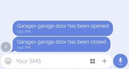
I wrote an Alexa skill in JavaScript (brand new to me, so thanks YouTube) using AWS Lambda which connected to AWS IoT and was able to write and read from the Garage Shadow in the cloud. I wrote a second Lambda function that subscribed to updates in this shadow, thanks to the AWS IoT Rules engine, and translated them into human-readable text messages. Thus, I would be alerted by SMS any time the garage door was opened or closed.
A block diagram of the new system
Video of the Functional Prototype
Now we were in business.
https://youtube.com/watch?v=axTEq9mnIOg%3Ffeature%3Doembed
Building the Device
With the full loop working it was time to start un-breadboarding (if that’s a term). I found this enclosure on Amazon which came with a PCB.
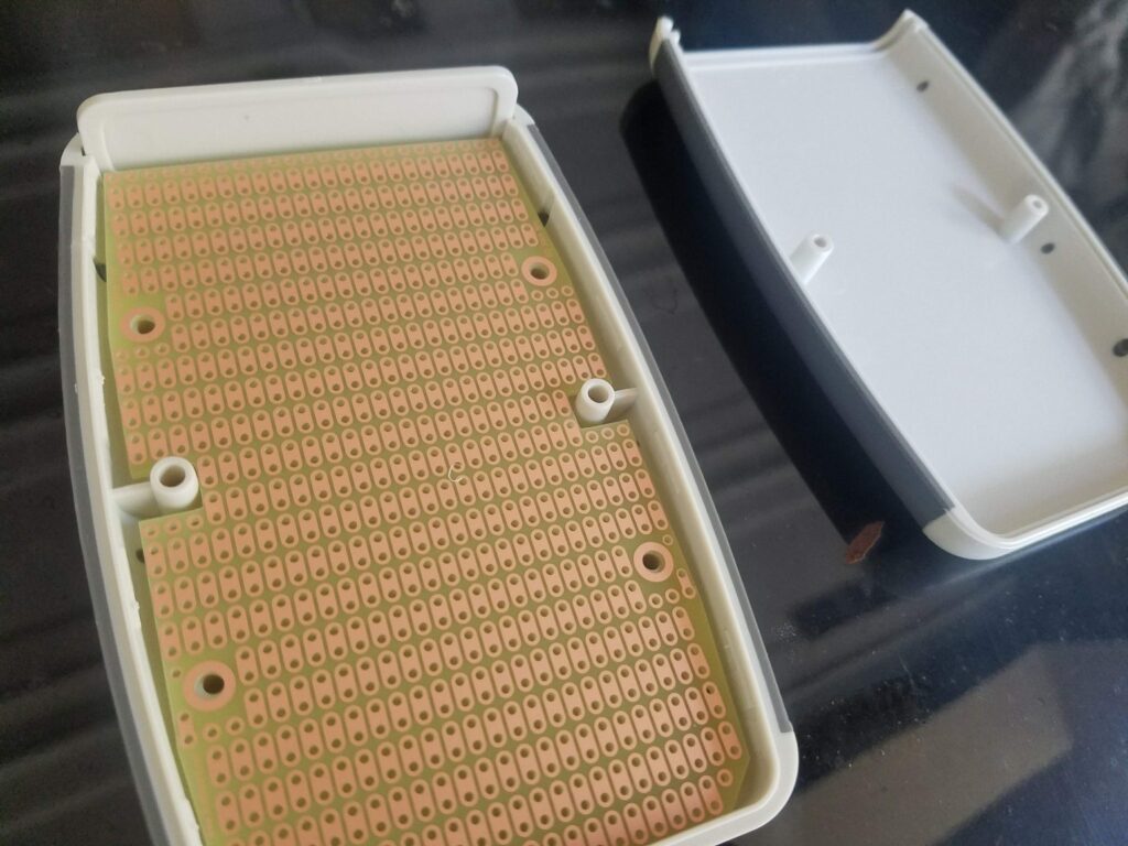
I found a right- angle microusb cable for the ESP8266 and wired it to a breakout microUSB PCB so that I could get access to the 5V right from the cable eliminating the need for a spare supply.
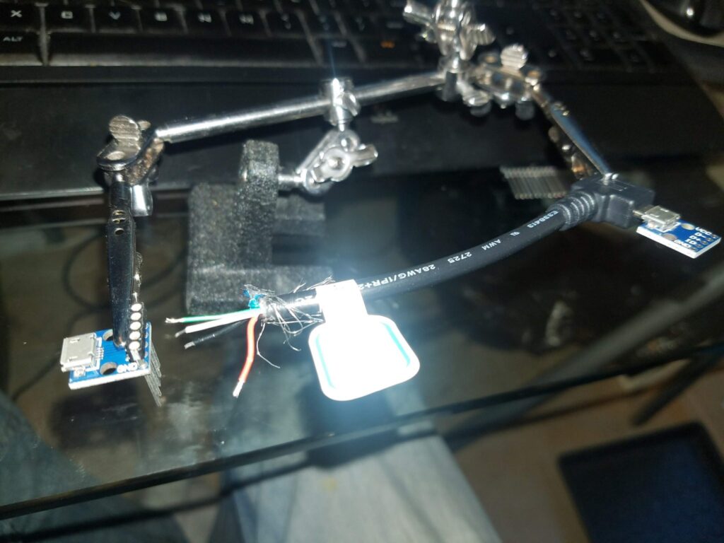
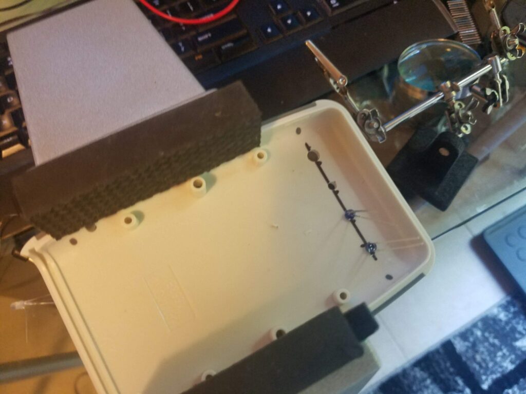
Drilled some holes for the LEDs…
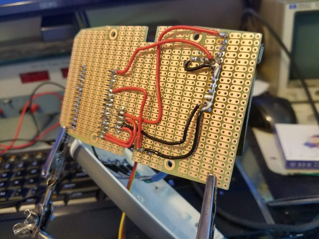
Started soldering the circuit…
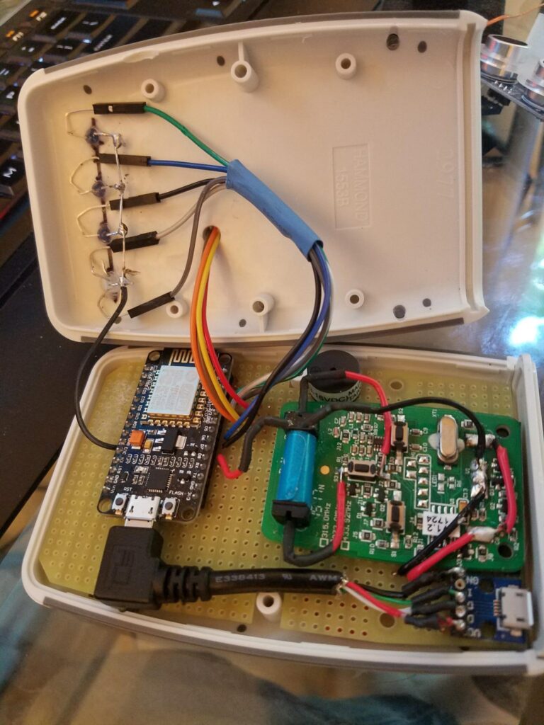
Tight fit!
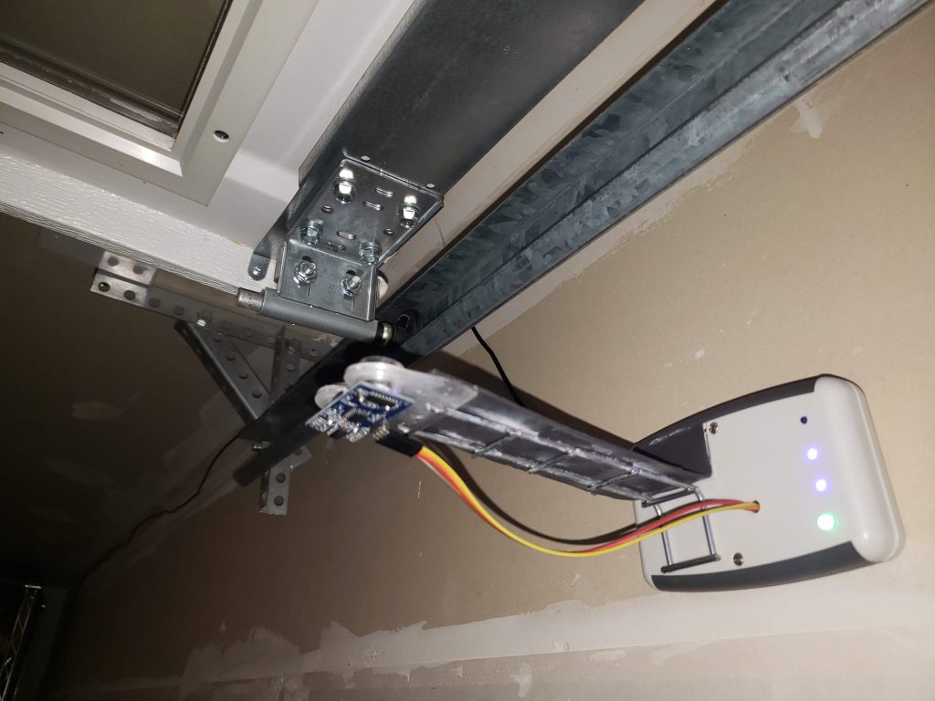
For mounting the sonar sensor in a rigid way, I hacked apart an old dog crate.

And thus the garage module was born!
Video of the Device
Below is a video of the full system
Video of the Raspberry PI Application
Below is a video of the system in more detail. It presents more of a “debug view” and shows off the Raspberry PI ‘middleman’ application, including communication to the AWS IoT shadow.
Github Links
Embedded code within the garage module:
https://github.com/BogdanovL/GarageMonitor
Raspberry PI server application
Note the ‘certs’ folder is purposefully missing from this repository. Also, a file called aws_iot_config.h is missing from the src folder. It can be found here and filled in by a user as necessary.